
Introduction to Networks
Networking can feel overwhelming at first, so I put together a condensed summary covering what actually transpires across the wire. If you'd like the full compilation of my CCNA notes, you can access it here.
The Open Systems Interconnection model (OSI model) was developed in the 1970s to help categorize the communication functions occurring at each layer of a network. Its purpose was to provide readers with a structured understanding of how systems communicate. From the bottom up, these layers are:
- Physical
- Data Link
- Network
- Transport
- Session
- Presentation
- Application.
I’ve found the mnemonic Please Do Not Teach Students Pointless Acronyms to be a helpful way to remember them.
Media primarily travels in three forms:
- Electrical (copper)
- Fiber (light)
- Wireless (radio transmission)
When discussing the Physical layer, we refer to hardware components, but it also includes signaling and encoding methods.
Encoding defines the voltage and current patterns used to represent binary values of 0 and 1. Ethernet, RFID, and NFC commonly use Manchester encoding, where bits are represented through transitions between logical states rather than neutral or resting positions — a signal either changes state, or it does not.
Error rates are minimized by this method through signal synchronization, and all this means is that signals are sent along a clock at an evenly spaced duration, or bit time. The other signal transmission method is asynchronous, which happens without this associated clock, making spacing arbitrary, and requiring START and STOP flag indicators for frames.
Modulation, the process where one signal modifies the characteristics of another for transmission, uses different techniques in data transmission, most commonly frequency, amplitude, and pulse-code modulation.
With frequency and amplitude modulation techniques, the carrier frequency varies in accordance with signal. With pulse-coded modulation, we see analog (voice) signals converted to digital ones through sampling and expressing different amplitudes in binary.
The big takeaway? Representations of bits depend on signaling method.
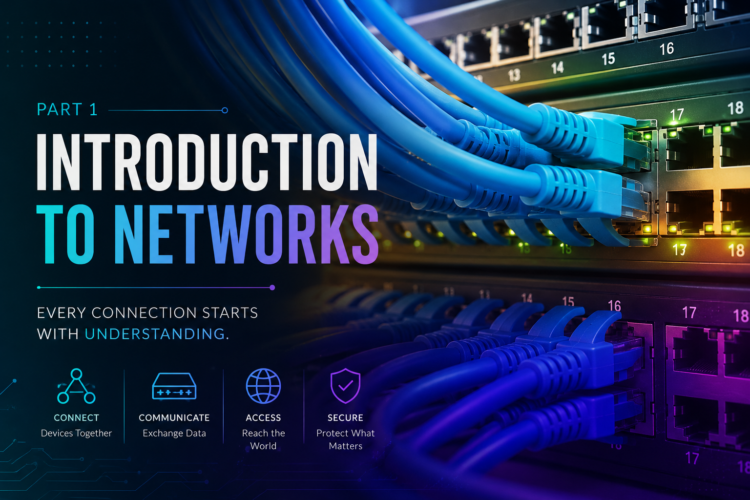
Bandwidth & Cabling
People often have awkward interpretations of what bandwidth means, but the base definition is the capacity of a medium to carry data from one place to another. When measuring how many bits successfully travel across media, we’re referring to throughput and the farther a signal has to travel, the more it attenuates, or naturally deteriorates, over distance.
Interference is commonly caused by electromagnetic or radio-frequency issues that distort signals, which is why proper shielding, cable termination, and handling practices are important for reducing transmission problems.
I won’t dive too deeply into the cabling material covered in the CCNA since most of it can be easily referenced, but there are a few fundamentals worth remembering.
With copper media, the primary cable types include unshielded twisted pair (UTP), shielded twisted pair (STP), and coaxial cable, all of which follow requirements defined by physical standards.
You should also be familiar with common CAT5 pinouts (orange-white, orange, blue-white, blue, green-white, green, brown-white, brown). RJ-45 connectors contain four pairs of color-coded wires twisted together inside a plastic sheath, which helps reduce signal interference and crosstalk (when opposing twisted wire pairs cancel each other out).
There are specific wiring conventions used for cabling, including straight-through, crossover, and rollover cables.
- Straight-through cables use the same termination standard on both ends, meaning each side is wired using either 568A or 568B.
- Crossover cables use opposite standards on each end.
- Rollover cables are Cisco-specific and are primarily used for console connections to routers and switches.
- Coaxial cables are insulated with a copper braid, surrounded by plastic shielding and terminate with F/N and BNC connector types.
Earlier, I mentioned that fiber transmission relies on light. To get a rough idea of how delicate these strands are, think of those fiber-optic novelty lamps people sometimes buy for decoration.
Because fiber uses light instead of electrical signaling, the cable design is slightly different. At the center is a pure glass core that carries light pulses, surrounded by a cladding layer that acts like a mirror, reflecting the light internally through a process known as total internal reflection.
Fiber media generally uses either lasers or Light Emitting Diodes (LEDs) as light sources. On the receiving end, photodiodes — electronic semiconductor devices — detect these light pulses, convert them into electrical voltages, and reconstruct the transmitted data into frames.
Fiber is broadly categorized into two types: Single-mode and multi-mode, which offer different perks. Single-mode fiber has light running down the center of a small core, while multi-mode uses the reflection of light to bounce inside the fiber and create multiple paths. It also uses a larger core with LED emitters. The key difference between the two is dispersion, or the spreading out of a pulse over time (more dispersion means greater signal loss and less distance).
There are also three main connector types to be familiar with: Straight-tip, subscriber and lucent, even though others exist. Common termination and splicing issues deal with misalignment, finishes and end gaps, which happen when media doesn’t completely touch at a connection. End finishes implies there could be some dirt or lack of polishing at a termination somewhere. You can test for issues with flashlights and Optical Time Domain Reflectometers.
Wireless media carries binary digits represented in electromagnetic signals using radio and microwave frequencies. The IEEE can be used for reference, but 802.11 WLAN, which uses CSMA/CA (Carrier Sense Multiple Access/Collision Avoidance), 802.15 WPAN (Wireless Personal Area Network) for Bluetooth, and 802.16 WiMAX (Worldwide Interoperability for Microwave Access) uses a point-to-multipoint topology.
The Data Link Layer
Data link provides structure to the 1’s and 0’s that travel across media and performs two very important functions which are sub-categorized into two areas.
The Logical Link Control accepts packets and then packages units into frames, portioned at the upper sub-layer, defining the processes that provide services to network layer protocols by placing information into frames that identify the protocol being used. Media Access Control handles error detection and is positioned at the lower sub-layer, defining media processes performed by hardware.
At each hop, a router accepts frames, de-encapsulates them and then re-encapsulates those packets into newer frames, which are forwarded to a network segment. Think of encapsulation as placing a letter within an envelope. Your letter contains important information and in order to get to where it needs to be, it has a stamped address. These frames are similar in the sense that they have a header which controls information and addressing, a data portion that holds the IP and a trailer for error detection.
The error detection mentioned above is important because it helps with issues seen in both wireless and copper. CSMA (Carrier Sense Multiple Access) helps detect if media is carrying a signal and gives a “busy response” if it sees something is trying to transmit, before trying again. If a collision occurs, everything is dropped and needs to be resent.
CSMA has two primary methods of handling and resolving issues with transmission: CSMA/CD (Collision Detection) and CSMA/CA (Collision Avoidance).
Collision Detection (CSMA/CD), traditionally used by Ethernet, works by having end devices listen for signals before transmitting. If no signal is detected, transmission begins. If a collision occurs, or multiple systems attempt to transmit simultaneously, communication stops and the devices retry transmission later.
Collision Avoidance (CSMA/CA), commonly used in wireless, takes a different approach. Devices first check whether the medium is in use and, if clear, sends a request indicating intent to transmit. Once acknowledgment is received, data is sent.
Transport
Transmission Control Protocol (TCP) and User Datagram Protocol (UDP) function at the transport layer and are responsible for how applications communicate simultaneously with each other. The key distinction between the two protocols is that TCP is connection oriented and UDP is connectionless.
Each have given strengths and tradeoffs. TCP prioritizes reliability by handling sequencing, acknowledgements, and error checking, while UDP sacrifices those in exchange for lower overhead and faster transmission speeds, making it ideal for streaming and real-time communication.