
A Phone Story
Many of us remember playing telephone and learning about attaching cans to a string and speaking through them as kids. That’s what’s known as the lover’s phone and was created sometime in the 16th century by a guy named Robert Hooke. The next 200 years or so became wrought with individuals working on similar telephony ideas, so history is less clear on the actual inventor of the phone and holds a debate on “who did it first”. We’re taught that Alexander Graham Bell created the first phone, but there are actually six individuals behind it all, so it’s more accurate to say he held the first US patent for his inventions.
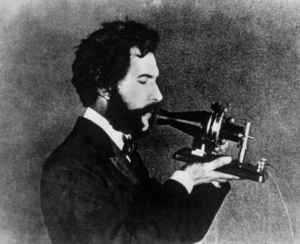
Antonio Meucci started building telephone-like devices around 1854 and Tivadar Puskas, was a Hungarian pioneer in the field who invented the switchboard. Johann Philipp Reis, created the Reis telephone in 1860 and of course Thomas Edison is tossed into the mix as well. The two biggest contenders in the debate for who created the phone however, are between a man named Elisha Gray, and Alexander Graham Bell. I won’t get into too many of the specifics here, but Gray was an electrical engineer who co-founded the Western Electric Manufacturing Company in 1872, and is credited with creating a phone prototype, although if you look at Reis’s work, you’ll find similarities in design. By 1876 he used a water microphone to create a telephone in Illinois, which was the same time Alexander Bell received the first US patent for the telephone, forming the American Bell Telephone Company just one year prior. Bell is credited with the first voice transmissions over wire, but you can find out more about the controversy here.
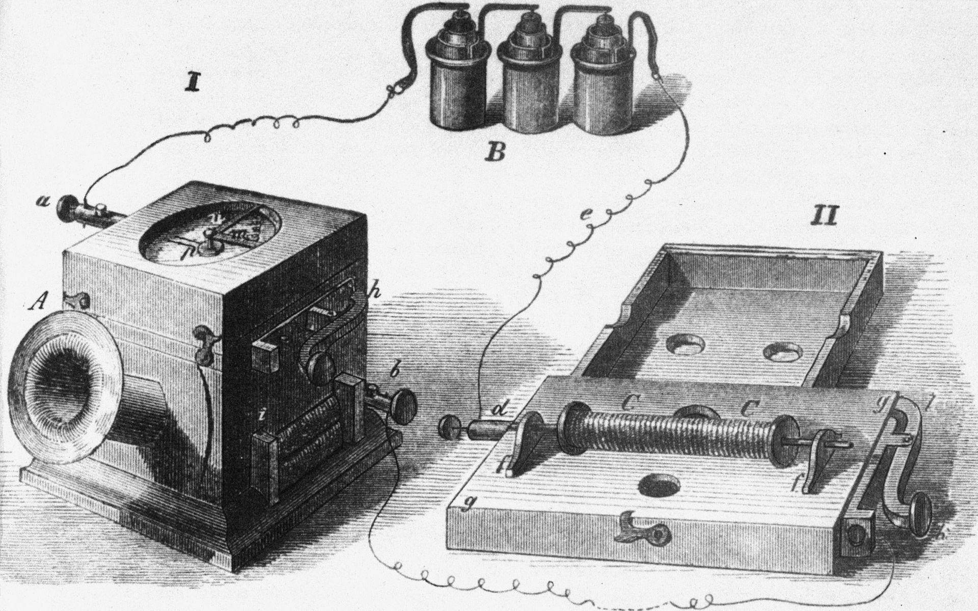
With that out of the way, let’s go over the first voice transmission, because number dialing and ringing didn’t exist just yet. It was similar to the lover’s phone mentioned earlier, and consisted of a physical wire that connected two devices. Users had to whistle into the phone in order to speak, which Bell added to make signaling easier. A needle was wired to a battery and current passed between contacts so that sound waves were converted into an electrical signal, which traveled to the receiver. More specifically, it was a carbon microphone, battery, electromagnet, iron diaphragm and physical cable between each location. The problem with Bell’s design was that it wasn’t scalable, so a few years later Bell developed a way to map phones without direct connections, or what we now know as the switch.
Before I get back to switches, I’m going to cover some important ground. The Public Switched Telephone Network provides a variety of services, but it’s also known as the Plain Old Telephone Service, or POTS for short, which is the basic phone standard. PSTN’s use voice-based networks that share circuits through packet switching. Phone lines, fiber-optics, microwave transmissions, cellular and satellites all fit within this broad spectrum of categories, but switching centers allow phones to communicate with each other. Originally this meant networks worked with fixed-lines and analog systems, but this converted to digital over time. A Central Office handles local loops and circuit switching in a given area that provides service to users. Terminals with these central office switches are used to make call decisions, with a single pair of wires that can carry one conversation.
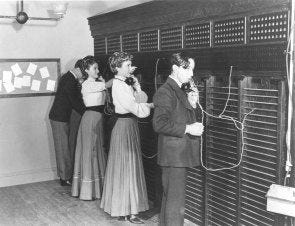
In another post, I briefly touched up on what trunks are, but they’re just a way of providing paths between switches, so we’re going to go back to the part of the story where Bell created the first switch. Switches were much more scalable to work with because they provided central offices a way to bring localized phone services to people. Operators built networks, sold services to customers, and many companies worked with the government to create monopolies like AT&T. These operators had to handle large switchboards with two pin connection sockets, known as jack sockets, for every pair of wires that existed. Users could ring the operator, give them the name and number of the party they were trying to reach, and the operator would connect a patch cord between two phones so that the receiver would ring.
Now I’m going to fast-forward a bit into the story with the introduction of automation because pulse dialing between phone exchanges and address signaling through SS7 comes into play (I’ll explain later). Agner Krarup Erlang, a Danish mathematician and engineer, helped create a foundation for a mathematical method to help with QoS (Quality of Service) related issues when it came to phone systems. The 1970’s brought the telecommunications industry packet-switched services with the X.25 protocol and the 1980’s brought in B-ISDN, or the Broadband Integrated Services Digital Network. This is also where we start to see DSL, ISDN, FTTx and cable modems; along with, things like Private Branch Exchanges (PBX) and Key Systems.
PBX’s are analog and digital phone switches that have been used to connect both private and public phone networks with each other. It’s basically a small CO switch companies can use for business, much like a personalized PTSN, that reduces the number of lines needed to be leased by a phone company. Every phone gets wired to the PBX and users have to dial 9 to make calls. Key Systems are a bit different in that they're defined by line selection buttons for each phone connected and that they aren't technically switches. These buttons light up when phones are in use and were designed for small companies.
Signaling Types
This is where things start to get a little more interesting because we have what’s known as in-band and out-of-band signaling with phone systems. The major distinction between the two signaling methods is that in-band deals with signaling in the same communications channel as voice, while out-of-band deals with communications and voice in separate channels. There are also three primary signaling types used in telephony and they are: Supervisory, which communicates the state of a device, address, which sends information about digits dialed and informational, which let’s the current state of a call be known.
When someone makes a phone call, they lift up a handset from their phone which triggers a switch to close, and starts a current flowing notifying the phone company. This would be the supervisory signaling type mentioned above. Shortly after, a phone company would send a dial tone to indicate that it’s ready to receive digits and the informational signaling type would be handled. Lastly, the person making the call, would start to press numbers, or use the address signaling type.
Address signaling can be also further categorized into two primary sub-types: DTMF, or Dual Tone MultiFrequency dialing, and Pulse. With DTMF, buttons on a keypad of the phone need to be pushed when you make a call and each is associated with a range of frequencies. Rotary, or pulse dialing phones contain a wheel that needs to be rotated and spun in order to send these numbers to make a call at a specific rate. Each pulse has a break and make segment, which signals the time circuits are open and closed.

Signaling System 7 and Common Channel Signaling
Common Channel Signaling, or CCS, is a system that uses a statistical multiplexing protocol in phone networks. Each specified channel is exclusively designed to carry signaling information and SS7 is an example of this. SS7 is a standard that has been used with ISDN, or the Integrated Services Digital Network, created in 1975 by Bellcore. It’s also the only international protocol defined by ITU-T’s Q.700-series recommendations, and is part of a suite of protocols called SIGTRAN, which uses SCTP, or Stream Control Transmission Protocol. Earlier versions, like SS5 used in-band signaling methods and bearer channels (this means call information was setup by sending it through multi-frequency tones in phone lines). These systems were exploited with devices like blue boxes that played the tones needed to control call routing. With SS6 and SS7 however, out-of-band signaling was implemented and helped keep voice channels separated.
As you learn about Voice over IP, FXS (Foreign Exchange Station), FXO (Foreign Exchange Office) and E&M, which have variations in voltage, will become terms you should familiarize yourself with. It’s important to know that FXS and FXO’s are always paired, and that without a PBX, phones are directly connected to FXS ports with RJ-11 (telephone) cables. FXS ports simulate CO’s, while FXO ports connect voice gateways to CO switches, or analog ports on PBX’s.
Digital Circuits and Analog Signals
There’s a few things that go on when it comes to digitizing analog signals, but sampling, quantization and encoding are all part of the process. When we sample an analog signal at periodic intervals, the output is a PAM, or Pulse Amplitude Modulation, whose rate has to be two times the highest frequency in order to produce smooth playback. Quantization matches PAM signals on a segmented scale and assigns integers to define amplitude. It’s basically a scale of multiple chords, each subdivided into equally spaced steps. Lastly, we convert signals which gives output in binary, each bit being either 0 (no pulse), or 1 (pulse).
Digital Signal Processors, or DSP chips perform the sampling, quantization, encoding mentioned above, along with compression when digitizing signals. An electronic circuit compresses voice, generates tones and decodes them. With Cisco routers, DSP’s are implemented through PVDM (Packet Voice DSP Modules).
Real-Time Transport, or RTP is a protocol commonly used with networks, so if you feel like experimenting, you can setup a VoIP phone and follow streams in Wireshark to hear messages. RTP is used to carry voice and video across networks with RTCP (RTP Control Protocol) being used for feedback on streams.
Codecs You Should Know
There are a few codecs you should be aware of when learning VoIP, but I’ll only list a few: G.711 (Pulse Code Modulation), G.729 (A standard for IP PBX) and iLBC (Internet Low Bitrate Codec), each have their pros and cons. Other things to learn and be aware of is H.323, H.3x, and SCCP (Skinny Client Control Protocol) and SIP, or Session Initiation Protocol, which is a standard for interactive multimedia sessions, which I won’t drone on about the details of.
This wouldn’t be a completely network-nerdery sort of post if I didn’t include some Cisco related commands, so I tossed a few up, but you’ll have to figure these out while you’re learning. 😉
I hope that people who read this piece were able to get something interesting out of it! Happy learning!
// Configuring CME to Support Endpoints
router(config)telephony-service // Enters telephony-service mode
router(config-telephony)max-ephone max-ephones // Sets max # defined by router

(config-telephony)max-dn maximum-directory-numbers // Sets max # of dns
router(config-telephony)ip source-address IP [port port] // IP-port for CUCM
router(config-telephony)auto-reg-ephone // Enables auto registration of new ephones

/* POTS Dial Peers Example */
router(config)dial-peer voice 20 pots
router(config-dialpeer)destination-pattern 1234
router(config-dialpeer)port 1/0/1